
FHL-VAC® Modules & Panels
FHL-VAC® Free Radiating Cylindrical Insulation Segments With ROB & SOB Heaters
Surface-hung free-radiating elements on cylindrical modules — maximum power in round furnaces.
FHL-VAC® Free-Radiating Cylindrical Insulation Segments feature pre-embedded hooks on the segment surface to support heating elements along the cylindrical module. This free-radiating configuration allows the elements to radiate heat directly into the furnace chamber, while the low-mass insulating structure minimizes heat loss to the surrounding atmosphere, enhancing thermal efficiency and supporting rapid heating response.
 1150 – 1550°C
Key features
Free-radiating surface-mounted elements for maximum heat flux
FHL® single-core ROB, FHL-MULTICORE® ROB and SOB options
Quick element replacement without disturbing the lining
High Dense Refractories for hearths and high-wear zones
From ID 100 mm up to customer requirement
Three grades up to 1550°C
Custom-Built Parameters
- Thickness
- 90 / 100 / 125 mm
- Inner diameter
- From ID 100 mm up to customer requirement
- Heater types
- FHL® Single-Core ROB · FHL-MULTICORE® ROB · FHL® SOB
Typical Applications
Technical data
Published grade data for FHL-VAC® insulation and FHL® heaters. Values are typical for the grade; confirm design values with our engineers for your duty cycle.
Technical Data — FHL-VAC® Modules & Panels
| Parameter | FHL-M 1150 | FHL-Z 1325 | FHL-HT 1550 |
|---|---|---|---|
| Classification Temperature (°C) | 1260 | 1425 | 1650 |
| Max. Continuous Working Temp. (°C) | 1150 | 1325 | 1550 |
| Density Range (kg/m³) | 200 – 240 | 200 – 240 | 200 – 240 |
| Linear Shrinkage % (24 h at Continuous Working Temp.) | < 1 | < 1 | < 1 |
Thermal Conductivity (W/mK)
| Mean Temperature | FHL-M 1150 | FHL-Z 1325 | FHL-HT 1550 |
|---|---|---|---|
| At 200°C | 0.065 | 0.065 | 0.065 |
| At 600°C | 0.13 | 0.13 | 0.14 |
| At 1000°C | 0.27 | 0.28 | 0.24 |
| At 1200°C | 0.40 | 0.38 | 0.33 |
| At 1300°C | 0.48 | 0.47 | 0.39 |
| At 1400°C | — | 0.53 | 0.45 |
| At 1500°C | — | — | 0.51 |
Chemical Composition (%)
| Component | FHL-M 1150 | FHL-Z 1325 | FHL-HT 1550 |
|---|---|---|---|
| Al₂O₃ | 47 | 37.5 | 66 |
| SiO₂ | 53 | 49.5 | 33 |
| Zr | — | 13 | — |
Physical & Mechanical Properties of FHL-MULTICORE® Heating Elements
Other elements present in small quantity. Values are typical for the grade; confirm design values with our engineers for your duty cycle.
| Fe-Cr-Al Heating Element | Ni-Cr 80 Heating Element | ||
|---|---|---|---|
| Property | Alloy 1 | Alloy 2 | Ni-Cr 80 |
| Standard Chemical Composition (%) | Al 5.0 · Cr 23 · Fe 72 | Al 6.0 · Cr 23 · Fe 71 | Cr 19–21 · Fe < 1 · Ni ≥ 77 |
| Max. Duty Temp. of Heating Element (°C) | 1320 | 1420 | 1150 |
| Electric Resistivity (Ω·mm²/m) | 1.35 ± 5% | 1.45 ± 5% | 1.08 ± 5% |
| Density (g/cm³) | 7.25 | 7.1 | 8.3 |
| Expansion from Thermal Factor (K⁻¹) | 15.1 × 10⁻⁶ | 14.8 × 10⁻⁶ | 17.6 × 10⁻⁶ |
| Thermal Conductivity at 20°C (W/m·K) | 13 | 13 | 13 |
| Specific Heat Capacity at 20°C (kJ/kg·K) | 0.46 | 0.46 | 0.46 |
| Melting Point (°C) | 1500 | 1500 | 1400 |
| Hardness Hv | 200 – 240 | 200 – 240 | 180 – 200 |
| Electric Resistance Temp. Coefficient | 33 × 10⁻⁶ | 15 × 10⁻⁶ | 58 × 10⁻⁶ |
| Increase from Oxidation 1200°C (mg/cm²·h) | 0.05 | 0.05 | 0.25 or less |
| Tensile Strength MPa (kgf/mm²) | 650 – 900 (65 – 90) | 650 – 900 (65 – 90) | 700 – 900 (70 – 90) |
| Magnetic Properties | Magnetic (Curie point 600°C) | Magnetic (Curie point 600°C) | Non-Magnetic |
Related products
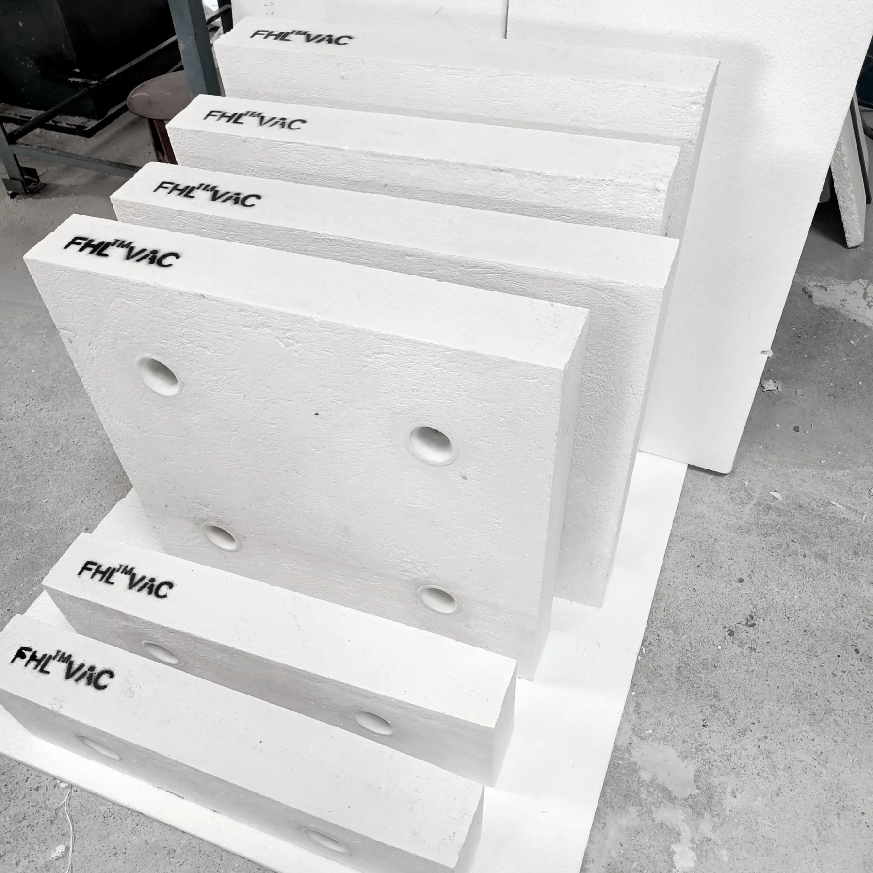 Up to 1200°C
FHL-VAC® Modules & Panels
FHL-VAC® Flat Insulation Panel
Rigid, vacuum-formed ceramic fiber panels for lightweight, energy-efficient furnace insulation.
View specifications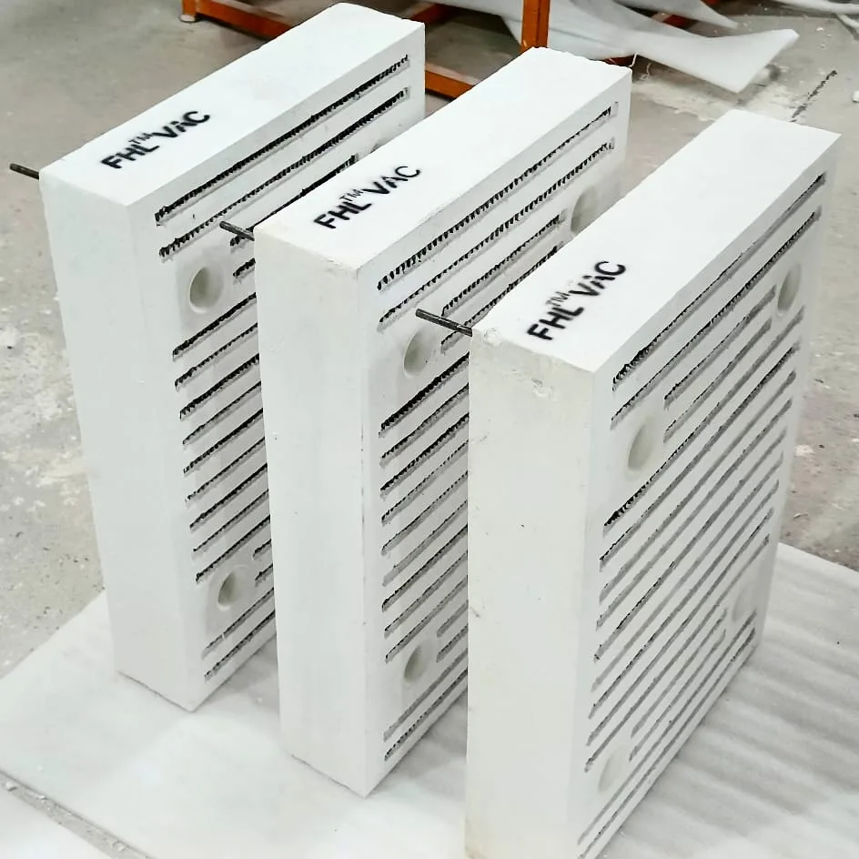 Up to 1050°C
FHL-VAC® Modules & Panels
FHL-VAC® Embedded Flat Heating & Insulation Panels
Heating element embedded inside the insulating module — a complete heated wall in one panel.
View specifications 1150 – 1550°C
FHL-VAC® Modules & Panels
FHL-VAC® Free Radiating Flat Insulation Panel With ROB & SOB Heaters
FHL-VAC® free-radiating panels with surface-suspended FHL-MULTICORE® ROB & SOB heaters for maximum power density.
View specificationsLet's build your upgrade
Need Free Radiating Cylindrical Segments built to your drawing?
Send us your chamber dimensions, temperature and cycle — we will respond with a technical proposal and quotation.